
Contactors
A contactor is defined according to IEV ref 441-14-33 as a mechanical switching device with only one rest position, operated other than by hand, capable of switching on, conducting and breaking currents under normal circuit conditions including operational overload.
In common parlance, this usually refers to an electromechanical contactor where the operation of switching on and off is done by means of an electrically driven coil. Simply put, the contactor is essentially a switch for electrical power in the same way that a relay is a switch for electrical signals or small loads.
With electrification and higher voltages in systems, contactors capable of extinguishing the resulting arc are required to safely interrupt the current, even under load in an emergency. It is therefore important to have the right contactor for the purpose. Factors to consider when choosing a contactor are current, voltage, current direction, inductance, short-circuit current, etc. This is to ensure that the current is actually broken and does not lead to more catastrophic events such as fire or similar, read more about risks here. Please contact us for help in choosing a contactor for your system.
See our range of contactors and contacts here

For each contactor, there is a short-circuit current and a time that it must withstand. If this is higher and longer than the specification, there is a risk that the contactor will weld together. What happens is that the magnetic field in the contact bridge forces the contact bridge apart and small arcs can form with the subsequent risk of the contactor welding the contact bridge. Alternatively, the heat in the contact points can be so high that they melt together.
Historically, contactors have been used to directly switch on and off electrical loads, such as electric motors, and even today they are used this way in many applications. In modern systems, however, starting and stopping is often done electronically and the purpose of the contactor is mainly to enable galvanic separation and to act as a switch in the event of an abnormality or fault in the system.
NO = Normally Open, NC = Normally Closed. This describes the state of a contactor when the voltage in the system is off. Normally open (NO) is mostly used in electrical systems where, for safety reasons, you want to be sure that the contactor opens when the power is cut in the system in case of a power failure. Normally Closed (NC) is often used when you want to be sure that the contactor closes a circuit in the event of a voltage drop, such as a power failure. to drain the system of energy to earth.
Read more about our DC contactors for both high and low voltage here.
With a contactor, you want to break the current safely and get rid of the arc that forms as quickly as possible. Since an arc occurs due to potential difference, the arc breaks itself in an alternating current (AC) application when the voltage crosses zero. In the case of direct current (DC), the current is constantly above zero and is therefore more difficult to break.
In the switching sequence, you want to increase the voltage in the arc to a higher voltage than that of the
the supply voltage
. This eventually eliminates the arc and stops conducting current. There are four ways to increase the voltage of the arc:

The most common way to achieve this is by using
magnetic blasting
.
An AC contactor is usually designed to break all three phases simultaneously, so there are three connection poles. However, since it is easier to break the alternating current, the design does not need to maximize the above-mentioned factors to increase the voltage in the arc. This means that the design of an AC contactor is simpler but takes up a lot of space.
One way to develop a DC contactor is to take an oversized AC contactor and build the poles so that it is single-pole but breaks the same pole three times. This is a technique that works, but the design is not optimal as the contactor becomes large and wears out quickly if it breaks under load.
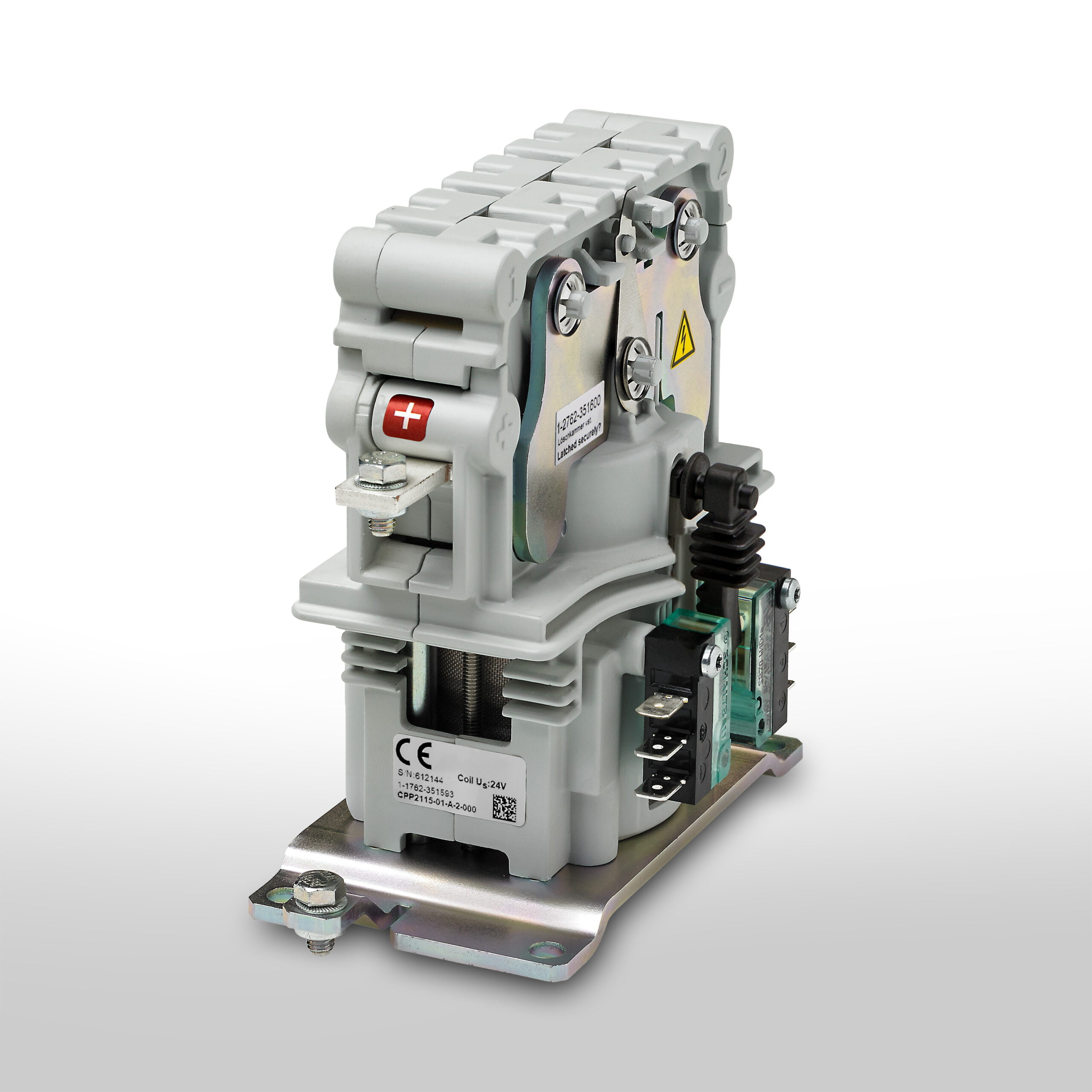
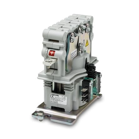
A robust DC contactor is usually designed to break one pole and optimized for that. But since breaking AC is more difficult, all four factors need to be maximized to increase the voltage. This is done here with a permanent magnet and an open arc chamber that has ceramic parts to split the arc. In addition, a design to pull it out and make it longer and narrower, as well as cooling it.
In each contactor there is a coil that operates switching and breaking, the voltage to control the coil can vary depending on the application, normally in industry is 24VDC. The contactor may also contain a PCB that controls switching on and off. Some contactors have more than one coil to reduce power consumption. Usually one more powerful to close the plug and one that draws less current to keep the plug closed. This has in modern Schaltbau contactors often been replaced by only one coil controlled by PWM signal to achieve lower power consumption and lighter contactor.
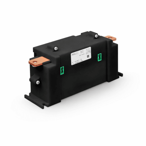
Pre-charge, in the context of a DC (direct current) system, refers to a process of gradually charging the capacitance or voltage level before the main power is switched on. The purpose of pre-charge is to reduce the initial current spike and thus avoid damage to the system and components.
When a DC system is started or reconnected after having been disconnected for a period of time, capacitances, such as for example capacitors, be fully discharged. Directly allowing the full voltage level to be applied to these capacitances can cause a sudden current spike that can be detrimental to components and the system as a whole. This current spike can be particularly problematic in power systems where high currents can cause disturbances or damage.
To avoid this, the pre-charge method is used. It involves gradually increasing the voltage level across the capacitances by using a limited current or a resistance-based power source. By slowly increasing the voltage across the capacitances, you can smooth out the current spike and protect the system. Once the voltage has increased to the desired level, the main power can be switched on and the system can operate normally.
Pre-charge is often used in areas such as power transmission, electric power systems and similar DC systems where capacitances may be present and current spikes should be avoided to protect equipment and ensure proper operation. In such a circuit, a pre-charge contactor is used.
SPST stands for “single-pole single-throw” and SPDT stands for “single-pole double-throw.” These abbreviations are often used for electrical switches, relays and microswitches.
Relays are classified by number of poles and number of throws. The “poles” of a micro switch, for example, are the terminals common to each path the current can take. Any position where a ‘pole’ can be connected is called a ‘throw’. The relays are also set as NO or NC. Read more here about what NO and NC means.
SPST is the most common form and has a ‘pole’ and a ‘throw’. Like a regular light switch at home. It is illustrated as follows:

The SPDT has a double throw and is illustrated as follows:

SPDT is good as a feedback signal as you can get both normal mode and mirrored mode from e.g.. a high voltage contactor. This always shows if the circuit is complete and the position of the main contactor when one pole is NO and the other NC. Both cannot be activated at the same time but follow the “break before make” concept.
Read more about our microswitches here.
Schaltbau’s micro switch:


Contactors

Contactors
Contactors

Contactors

Contactors

Contactors

Contactors

Contactors
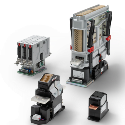
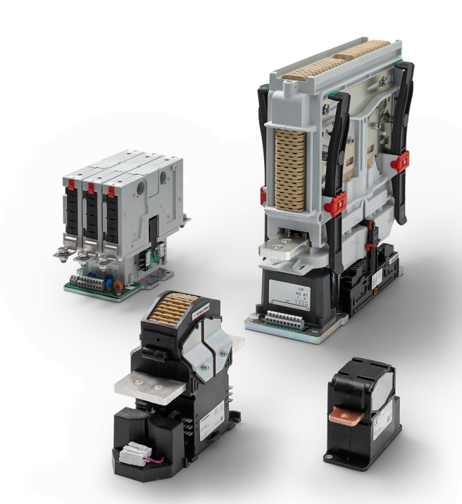
Our range of DC and AC contactors ranges from battery voltage contactors to high power contactors up to 4800 V and 2000 A.
The safest DC contactors on the market with air-based arc suppression from Schaltbau for all applications where a circuit must be safely closed or disconnected. Especially for applications in trains and modern battery systems with high voltage DC as our contactors are fully bidirectional making them suitable for both charging and discharging over the same contactor.
Our DC contactors are used for example in applications such as trains, industrial storage systems (ESS), marine systems, automotive and other E-mobility.