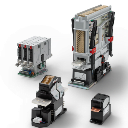
Contactors

This question must be broken down into several parameters. The amount of current that can flow through the contactor continuously is determined by the heat dissipation capacity and the maximum continuous current is often referred to as Ith or thermal current. Often a higher current can be run for a shorter time.
When switching off or breaking under load, an arc is always created. The energy in the arc is determined by the current and voltage and the type of load being broken. The arc is ionized gas, s.k. plasma. The energy of the arc is very high and powerfully destructive for the e.g. the contacts. Depending on the design, the contactor can handle the arc in different ways. The aim is always to cool the energy in the arc to create a safe situation and reduce wear and tear. The breaking capacity is always given in amperes at a specific voltage and time constant of the load.
When switching under load, small arcs may form but these disappear as soon as the contact is closed. The capacity for switching is often much greater than for breaking and is given in amperes at a specific voltage and time constant for the load.
In each contactor there is a coil that operates switching and breaking, the voltage to control the coil can vary depending on the application, normally in industry is 24VDC. The contactor may also contain a PCB that controls switching on and off. Some contactors have more than one coil to reduce power consumption. Usually one more powerful to close the plug and one that draws less current to keep the plug closed. This has in modern Schaltbau contactors often been replaced by only one coil controlled by PWM signal to achieve lower power consumption and lighter contactor.
Vacuum contactors use encapsulated contacts with vacuum instead of air as the medium to eliminate arcing. Vacuum contactors are only applicable for use in AC applications. The AC arc generated by the opening of the contacts will itself be extinguished at the zero crossing of the current waveform, the vacuum preventing a re-ignition of the arc across the open contacts.
With a contactor, you want to break the current safely and get rid of the arc that forms as quickly as possible. Since an arc occurs due to potential difference, the arc breaks itself in an alternating current (AC) application when the voltage crosses zero. In the case of direct current (DC), the current is constantly above zero and is therefore more difficult to break.
In the switching sequence, you want to increase the voltage in the arc to a higher voltage than that of the
the supply voltage
. This eventually eliminates the arc and stops conducting current. There are four ways to increase the voltage of the arc:

The most common way to achieve this is by using
magnetic blasting
.
An AC contactor is usually designed to break all three phases simultaneously, so there are three connection poles. However, since it is easier to break the alternating current, the design does not need to maximize the above-mentioned factors to increase the voltage in the arc. This means that the design of an AC contactor is simpler but takes up a lot of space.
One way to develop a DC contactor is to take an oversized AC contactor and build the poles so that it is single-pole but breaks the same pole three times. This is a technique that works, but the design is not optimal as the contactor becomes large and wears out quickly if it breaks under load.
A robust DC contactor is usually designed to break one pole and optimized for that. But since breaking AC is more difficult, all four factors need to be maximized to increase the voltage. This is done here with a permanent magnet and an open arc chamber that has ceramic parts to split the arc. In addition, a design to pull it out and make it longer and narrower, as well as cooling it.
The contactor can either be controlled to one mode or both modes, for switching on or off. For example, a monostable controls the switch-on by coil, while the switch-off is controlled by a spring if the coil voltage is broken. A bistable controls both striking and breaking with the coil. A bistable contactor uses no energy to keep the contactor in the respective position.
Read more about our contactors here.
A contactor is defined according to IEV ref 441-14-33 as a mechanical switching device with only one rest position, operated other than by hand, capable of switching on, conducting and breaking currents under normal circuit conditions including operational overload.
In common parlance, this usually refers to an electromechanical contactor where the operation of switching on and off is done by means of an electrically driven coil. Simply put, the contactor is essentially a switch for electrical power in the same way that a relay is a switch for electrical signals or small loads.
With electrification and higher voltages in systems, contactors capable of extinguishing the resulting arc are required to safely interrupt the current, even under load in an emergency. It is therefore important to have the right contactor for the purpose. Factors to consider when choosing a contactor are current, voltage, current direction, inductance, short-circuit current, etc. This is to ensure that the current is actually broken and does not lead to more catastrophic events such as fire or similar, read more about risks here. Please contact us for help in choosing a contactor for your system.
See our range of contactors and contacts here

Contactors

Contactors
Contactors

Contactors

Contactors

Contactors

Contactors

Contactors
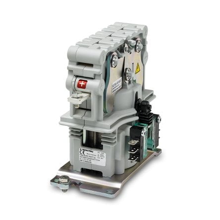
Multi-pole unidirectional contactor for DC or AC up to 800 V and 30 A
of continuous current for low and medium power applications, e.g. recharge or pre-charge circuit. Can be configured in several variants with or without aux. signal.