
Contactors
A contactor is defined according to IEV ref 441-14-33 as a mechanical switching device with only one rest position, operated other than by hand, capable of switching on, conducting and breaking currents under normal circuit conditions including operational overload.
In common parlance, this usually refers to an electromechanical contactor where the operation of switching on and off is done by means of an electrically driven coil. Simply put, the contactor is essentially a switch for electrical power in the same way that a relay is a switch for electrical signals or small loads.
With electrification and higher voltages in systems, contactors capable of extinguishing the resulting arc are required to safely interrupt the current, even under load in an emergency. It is therefore important to have the right contactor for the purpose. Factors to consider when choosing a contactor are current, voltage, current direction, inductance, short-circuit current, etc. This is to ensure that the current is actually broken and does not lead to more catastrophic events such as fire or similar, read more about risks here. Please contact us for help in choosing a contactor for your system.
See our range of contactors and contacts here

This question must be broken down into several parameters. The amount of current that can flow through the contactor continuously is determined by the heat dissipation capacity and the maximum continuous current is often referred to as Ith or thermal current. Often a higher current can be run for a shorter time.
When switching off or breaking under load, an arc is always created. The energy in the arc is determined by the current and voltage and the type of load being broken. The arc is ionized gas, s.k. plasma. The energy of the arc is very high and powerfully destructive for the e.g. the contacts. Depending on the design, the contactor can handle the arc in different ways. The aim is always to cool the energy in the arc to create a safe situation and reduce wear and tear. The breaking capacity is always given in amperes at a specific voltage and time constant of the load.
When switching under load, small arcs may form but these disappear as soon as the contact is closed. The capacity for switching is often much greater than for breaking and is given in amperes at a specific voltage and time constant for the load.
In each contactor there is a coil that operates switching and breaking, the voltage to control the coil can vary depending on the application, normally in industry is 24VDC. The contactor may also contain a PCB that controls switching on and off. Some contactors have more than one coil to reduce power consumption. Usually one more powerful to close the plug and one that draws less current to keep the plug closed. This has in modern Schaltbau contactors often been replaced by only one coil controlled by PWM signal to achieve lower power consumption and lighter contactor.
With a contactor, you want to break the current safely and get rid of the arc that forms as quickly as possible. Since an arc occurs due to potential difference, the arc breaks itself in an alternating current (AC) application when the voltage crosses zero. In the case of direct current (DC), the current is constantly above zero and is therefore more difficult to break.
In the switching sequence, you want to increase the voltage in the arc to a higher voltage than that of the
the supply voltage
. This eventually eliminates the arc and stops conducting current. There are four ways to increase the voltage of the arc:

The most common way to achieve this is by using
magnetic blasting
.
An AC contactor is usually designed to break all three phases simultaneously, so there are three connection poles. However, since it is easier to break the alternating current, the design does not need to maximize the above-mentioned factors to increase the voltage in the arc. This means that the design of an AC contactor is simpler but takes up a lot of space.
One way to develop a DC contactor is to take an oversized AC contactor and build the poles so that it is single-pole but breaks the same pole three times. This is a technique that works, but the design is not optimal as the contactor becomes large and wears out quickly if it breaks under load.
A robust DC contactor is usually designed to break one pole and optimized for that. But since breaking AC is more difficult, all four factors need to be maximized to increase the voltage. This is done here with a permanent magnet and an open arc chamber that has ceramic parts to split the arc. In addition, a design to pull it out and make it longer and narrower, as well as cooling it.
For each contactor, there is a short-circuit current and a time that it must withstand. If this is higher and longer than the specification, there is a risk that the contactor will weld together. What happens is that the magnetic field in the contact bridge forces the contact bridge apart and small arcs can form with the subsequent risk of the contactor welding the contact bridge. Alternatively, the heat in the contact points can be so high that they melt together.
High short-circuit currents and an unregulated closing with load is the most common reason for the contactor to weld. This is usually due to an insufficient pre-charge. Read more about Pre-charge here.
Excessive and high short-circuit currents can cause the contact bridge to lift and open due to the magnetic field generated by the current, called levitation. This can cause the contactor to weld because when the contactor bridge opens, micro arcing and extensive heating occur.
Breaking higher loads than the contactor is designed for, especially high inductance can cause the contactor bridge to weld.
Using silver oxide on the contactor pills increases the resistance to welding.
Read more about our contactors here.
NO = Normally Open, NC = Normally Closed. This describes the state of a contactor when the voltage in the system is off. Normally open (NO) is mostly used in electrical systems where, for safety reasons, you want to be sure that the contactor opens when the power is cut in the system in case of a power failure. Normally Closed (NC) is often used when you want to be sure that the contactor closes a circuit in the event of a voltage drop, such as a power failure. to drain the system of energy to earth.
Read more about our DC contactors for both high and low voltage here.


Contactors
Contactors

Contactors
Contactors

Contactors

Contactors

Contactors

Contactors
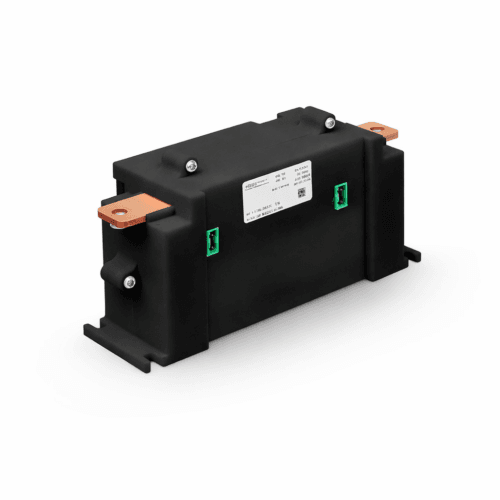
The C305 combines high performance with exceptional reliability and energy efficiency. The silver-alloyed contact surfaces offer very low resistance of only 50µΩ, minimizing heat generation and energy losses even at high currents. It is optimized to withstand megawatt-class charging (MCS). With its bi-directional design, it is fully ready for future energy recovery systems, such as Vehicle-to-Grid (V2G) solutions and advanced energy storage. The built-in energy saving feature contributes to lower operating costs, while the compact and robust design makes installation easy and enables long lifetime even in demanding environments.